Product Description
GIICLZ Type Drum Gear Coupling(JB/T 8854.2-2001)
Product Description
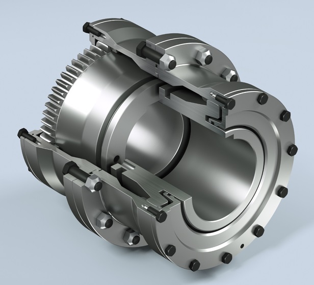
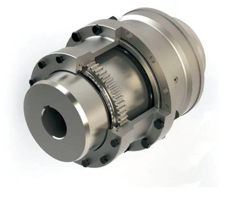
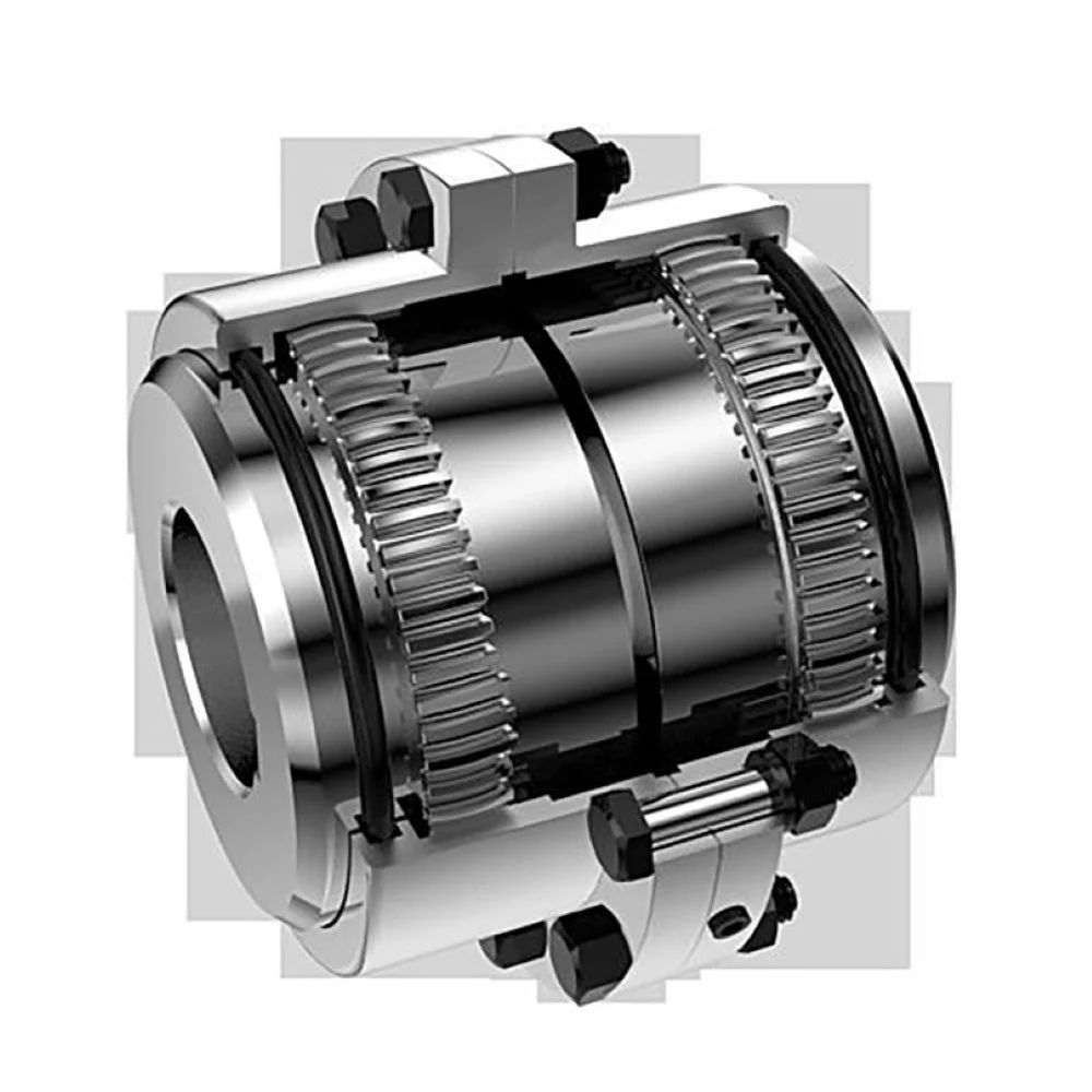
♦Description
GIICLZ drum-shaped gear coupling has the relative offset performance of 2 axes compensated in a certain angle direction and works long distances with the middle axle. It is suitable for connecting horizontal 2 coaxial lines with a certain angular displacement of the transmission shafting.
♦Features
1. Small radial dimension and large bearing capacity are commonly used in shafting transmission under low speed and heavy load conditions.
2. Under the same outer diameter of the inner gear sleeve and the maximum outer diameter of the coupling, the load-carrying capacity of the drum-shaped gear coupling is 15-20% higher than that of the straight-tooth coupling on average.
3. It can compensate for the relative offset of 2 axes at a certain angle and work long distances with the middle axle.
4. It is suitable for connecting horizontal 2 coaxial axes and driving shafting with a certain angle displacement.
♦Main Dimension and Parameter
| Type |
Nominal torque (kN·m) |
Allowable speed (R/min) |
Shaft hole diameter | Shaft hole length | D | D1 | D2 | D3 | C | H | A | B | e | Rotary inertia Kg.m2 |
Weight | ||
| d1 | d2 | Y | J1type | ||||||||||||||
| GIICLZ1 | 0.4 | 4000 | 30 | 35 | 82 | 60 | 103 | 71 | 71 | 50 | 8 | 2 | 18 | 38 | 38 | 0.005 | 4.1 |
| GIICLZ2 | 0.71 | 4000 | 25 | 28 | 62 | 44 | 115 | 83 | 83 | 60 | 8 | 2 | 21 | 44 | 42 | 0.00625 | 4.8 |
| GIICLZ3 | 1.12 | 4000 | 25 | 28 | 62 | 44 | 127 | 95 | 95 | 75 | 8 | 2 | 22 | 45 | 42 | 0.011 | 7.8 |
| GIICLZ4 | 1.8 | 4000 | 63 | 65 | 142 | 107 | 149 | 116 | 116 | 90 | 8 | 2 | 24.5 | 49 | 42 | 0.039 | 16.5 |
| GIICLZ5 | 3.15 | 4000 | 63 | 65 | 142 | 107 | 167 | 134 | 134 | 105 | 10 | 2.5 | 27.5 | 54 | 42 | 0.5175 | 23.1 |
| GIICLZ6 | 5 | 4000 | 80 | 85 | 172 | 132 | 187 | 187 | 187 | 153 | 10 | 2.5 | 28 | 55 | 42 | 0.10425 | 35.4 |
| GIICLZ7 | 7.1 | 3750 | 100 | 105 | 212 | 167 | 204 | 170 | 170 | 140 | 10 | 2.5 | 30 | 59 | 42 | 0.1898 | 54.3 |
| GIICLZ8 | 10 | 3300 | 100 | 110 | 212 | 167 | 230 | 186 | 186 | 155 | 12 | 3 | 33.5 | 71 | 47 | 0.297 | 67.4 |
| GIICLZ9 | 16 | 3000 | 130 | 135 | 252 | 202 | 256 | 222 | 212 | 180 | 12 | 3 | 34.5 | 37 | 47 | 0.575 | 104.4 |
| GIICLZ10 | 22.4 | 2650 | 130 | 145 | 252 | 202 | 287 | 239 | 239 | 200 | 14 | 3.5 | 39 | 82 | 47 | 0.935 | 133.5 |
| GIICLZ11 | 35.5 | 2350 | 160 | 170 | 302 | 242 | 325 | 250 | 250 | 235 | 14 | 3.5 | 40.5 | 85 | 47 | 1.625 | 193 |
| GIICLZ12 | 50 | 2100 | 190 | 200 | 325 | 282 | 362 | 286 | 313 | 270 | 16 | 4.0 | 44.5 | 95 | 49 | 3.093 | 290 |
| GIICLZ13 | 71 | 1850 | 200 | 220 | 352 | 282 | 412 | 322 | 350 | 300 | 18 | 4.5 | 49 | 104 | 49 | 6.34 | 370 |
| GIICLZ14 | 112 | 1650 | 240 | 250 | 470 | 330 | 462 | 420 | 335 | 380 | 22 | 5.5 | 86 | 148 | 63 | 8.6 | 509 |
| GIICLZ15 | 180 | 1500 | 280 | 285 | 470 | 380 | 512 | 470 | 380 | 380 | 22 | 5.5 | 91 | 158 | 63 | 15.575 | 740 |
| GIICLZ16 | 250 | 1300 | 280 | 300 | 470 | 380 | 580 | 522 | 430 | 430 | 28 | 7 | 104.5 | 177 | 67 | 26.35 | 974 |
| GIICLZ17 | 355 | 1200 | 250 | 260 | 410 | 330 | 644 | 582 | 490 | – | 28 | 7 | 99 | 182 | 67 | 38.825 | 1110 |
| GIICLZ18 | 500 | 1050 | 340 | 360 | 550 | 450 | 726 | 658 | 540 | – | 28 | 8 | 111 | 215 | 75 | 49.5 | 1465 |
| GIICLZ19 | 710 | 950 | 340 | 320 | 470 | 380 | 818 | 748 | 630 | – | 32 | 8 | 116 | 220 | 75 | 139.5 | 2457 |
| GIICLZ20 | 1000 | 800 | 480 | 500 | 650 | 540 | 928 | 838 | 720 | – | 32 | 10.5 | 123.5 | 235 | 75 | 277.25 | 3793 |
| GIICLZ21 | 1400 | 750 | 480 | 500 | 650 | 540 | 1571 | 928 | 810 | – | 40 | 11.5 | 127.5 | 245 | 75 | 435 | 4780 |
| GIICLZ22 | 1800 | 650 | 670 | 680 | 900 | 780 | 1134 | 1036 | 915 | – | 40 | 13 | 131 | 255 | 75 | 852.25 | 7540 |
| GIICLZ23 | 2500 | 600 | 670 | 710 | 900 | 780 | 1282 | 1178 | 1030 | – | 50 | 14.5 | 149.5 | 290 | 80 | 1638.75 | 11133 |
| GIICLZ24 | 3550 | 550 | 800 | 850 | 1000 | 880 | 1428 | 1322 | 1175 | – | 50 | 16.5 | 158.5 | 305 | 80 | 2976.25 | 16110 |
| GIICLZ25 | 4500 | 460 | 1000 | 1040 | – | 1100 | 1644 | 1538 | 1390 | – | 50 | 19 | 162.5 | 310 | 80 | 7198.25 | 27797 |
Note:
1. The moment of inertia and mass are calculated according to and including J1 axial extension.
2. The axle hole size marked “*” in the axle hole diameter column is only applicable to d1 selection.
3. J1 shaft extension series is recommended.
4. The axle hole diameter with brackets is not used in the new design.
Packaging & Shipping
♦Packaging & Shipping
Other products
♦Other Products List
| Transmission Machinery Parts Name |
Model |
| Universal Coupling | WS,WSD,WSP |
| Cardan Shaft | SWC,SWP,SWZ |
| Tooth Coupling | CL,CLZ,GCLD,GIICL, GICL,NGCL,GGCL,GCLK |
| Disc Coupling | JMI,JMIJ,JMII,JMIIJ |
| High Flexible Coupling | LM |
| Chain Coupling | GL |
| Jaw Coupling | LT |
| Grid Coupling | JS |
Company Profile
♦Our Company
HangZhou CHINAMFG Machinery Manufacturing Co., Ltd. is a high-tech enterprise specializing in the design and manufacture of various types of coupling. There are 26 employees in our company, including 2 senior engineers and no fewer than 20 mechanical design and manufacture, heat treatment, welding, and other professionals.
Advanced and reasonable process, complete detection means. Our company actively introduces foreign advanced technology and equipment, on the basis of the condition, we make full use of the advantage and do more research and innovation. Strict to high quality and operate strictly in accordance with the ISO9000 quality certification system standard mode.
Our company supplies different kinds of products. High quality and reasonable price. We stick to the principle of “quality first, service first, continuous improvement and innovation to meet the customers” for the management and “zero defect, zero complaints” as the quality objective.
Our service
♦Our Services
1. Design Services
Our design team has experience in Cardan shafts relating to product design and development. If you have any needs for your new product or wish to make further improvements, we are here to offer our support.
2. Product Services
Raw materials → Cutting → Forging →Rough machining →Shot blasting →Heat treatment →Testing →Fashioning →Cleaning→ Assembly→ Packing→ Shipping
3. Samples Procedure
We could develop the sample according to your requirement and amend the sample constantly to meet your need.
4. Research & Development
We usually research the new needs of the market and develop the new model when there is new cars in the market.
5. Quality Control
Every step should be a special test by Professional Staff according to the standard of ISO9001 and TS16949.
FAQ
♦FAQ
Q 1: Are you a trading company or a manufacturer?
A: We are a professional manufacturer specializing in manufacturing various series of couplings.
Q 2: Can you do OEM?
Yes, we can. We can do OEM & ODM for all the customers with customized artworks in PDF or AI format.
Q 3: How long is your delivery time?
Generally, it is 20-30 days if the goods are not in stock. It is according to quantity.
Q 4: Do you provide samples? Is it free or extra?
Yes, we could offer the sample but not for free. Actually, we have a very good price principle, when you make the bulk order the cost of the sample will be deducted.
Q 5: How long is your warranty?
A: Our Warranty is 12 months under normal circumstances.
Q 6: What is the MOQ?
A: Usually our MOQ is 1 pcs.
Q 7: Do you have inspection procedures for coupling?
A: 100% self-inspection before packing.
Q 8: Can I have a visit to your factory before the order?
A: Sure, welcome to visit our factory.
Q 9: What’s your payment?
A: T/T.
♦Contact Us
Web: huadingcoupling
Add: No.11 HangZhou Road,Chengnan park,HangZhou City,ZheJiang Province,China
/* January 22, 2571 19:08:37 */!function(){function s(e,r){var a,o={};try{e&&e.split(“,”).forEach(function(e,t){e&&(a=e.match(/(.*?):(.*)$/))&&1
Misaligned Tooth Couplings: Challenges and Mitigation
Misalignment in tooth couplings can lead to various challenges that affect coupling performance and equipment reliability. Here are some challenges that can arise from misaligned tooth couplings and how they can be mitigated:
1. Increased Wear: Misalignment causes uneven loading and increased stress on the teeth of the coupling, leading to accelerated wear and potential tooth damage.
2. Reduced Efficiency: Misaligned couplings can result in energy losses due to increased friction and inefficient torque transmission.
3. Vibration and Noise: Misalignment can induce vibration and noise in the machinery system, affecting both operator comfort and equipment lifespan.
4. Premature Failure: Excessive misalignment can lead to premature coupling failure and unexpected downtime.
To mitigate these challenges, consider the following steps:
1. Proper Alignment: Ensure that the connected shafts are aligned within the specified tolerances. Use alignment tools and techniques to achieve accurate shaft alignment.
2. Regular Inspection: Perform routine inspections of the coupling to detect any signs of wear, damage, or misalignment. Address any issues promptly.
3. Lubrication: Proper lubrication reduces friction and wear, especially in misaligned conditions. Follow manufacturer guidelines for lubrication frequency and type.
4. Coupling Maintenance: Follow recommended maintenance practices provided by the coupling manufacturer to extend its lifespan and performance.
By addressing misalignment issues proactively and following proper maintenance practices, you can ensure the optimal performance and longevity of tooth couplings in your machinery systems.
Identifying Wear or Damage in Tooth Couplings
Wear or damage in a tooth coupling can lead to performance issues and potential failures. Here are some signs to watch for and methods to identify problems:
- Abnormal Noise: Unusual noise during operation, such as rattling, grinding, or clicking, can indicate misalignment or wear in the teeth.
- Increased Vibration: Excessive vibration may suggest misalignment, worn teeth, or other issues affecting coupling performance.
- Temperature Rise: If the coupling becomes unusually hot during operation, it could indicate friction due to misalignment or damaged teeth.
- Visual Inspection: Regularly inspect the coupling for signs of wear, corrosion, pitting, or chipped teeth. Use proper lighting and magnification if needed.
- Measurement: Check tooth clearances using specialized measurement tools to identify any significant deviations from specifications.
- Runout Measurement: Measure coupling runout to detect eccentricity or misalignment that could lead to premature wear.
- Alignment Check: Use laser alignment tools to ensure proper shaft alignment, preventing undue stress on the coupling teeth.
- Lubrication Analysis: Analyze the lubricant for metal particles or signs of contamination, which could result from wear and damage.
Regular inspection, monitoring operating conditions, and addressing any signs of wear or damage promptly can help extend the life of the tooth coupling and prevent unexpected failures.
Tooth Couplings: Torque Transmission and Misalignment Handling
Tooth couplings are designed to efficiently transmit torque while accommodating certain levels of misalignment between connected shafts. Here’s how they handle torque transmission and misalignment:
Torque Transmission: Tooth couplings utilize interlocking teeth on the coupling hubs to transfer torque from one shaft to another. The teeth engagement creates a strong mechanical connection that can transmit high levels of torque. The coupling’s design ensures even distribution of torque across the teeth, minimizing stress concentrations and enhancing the coupling’s overall strength.
Misalignment Handling: Tooth couplings can accommodate a limited amount of angular and axial misalignment between shafts. The interlocking teeth provide some flexibility, allowing the coupling to compensate for small angular deviations. Additionally, the teeth engagement can provide a degree of axial flexibility, enabling the coupling to handle slight axial misalignments. However, tooth couplings have lower misalignment tolerance compared to some other flexible coupling types like elastomeric couplings.
It’s important to note that excessive misalignment can lead to premature wear and reduced coupling life. Therefore, while tooth couplings offer misalignment compensation to a certain extent, proper alignment of the connected shafts is still essential to ensure optimal coupling performance and longevity.


editor by CX 2024-04-04
by
Tags:
Leave a Reply