Product Description
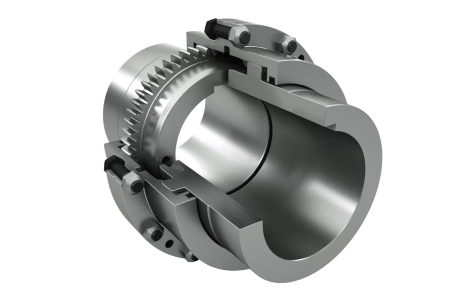
Restraint Stainless Steel Straub Pipe Coupling with Gear Ring
1. Product Introduction :
Our Stainless Steel Grip Straub Coupling is similar to STRAUB-METAL-GRIP which is a high performance coupling suitable for all pipe systems.
This Coupling is mainly used for building construction or civil engineering, power plants and etc .
This pipe joining coupling also absorbs unexpected field stress and applies perfect for seismic retrofits
Stainless Steel Straub Grip Type Coupling with Axial Restraint is used to join Metal Pipe to Metal Pipe or
Metal Pipe to Plastic Pipe or Plastic Pipe to Plastic Pipe .
All of our Coupling designated with GRIP have axial restraint .
In order to able to absorb the axial forces arising from the internal pressure,
anchoring teeth engage in the relevant pipe materials and provide a mechanical frictional connection.
If the axial tensile load on the pipe increases due to increasing internal pressure,
the teeth engage deeper inot the pipe surface .
These flexible and lightweight Couplings come fully assembled and can be installed without using any special tools .
2. Proudct Features :
* body, bolt, nuts made of stainless steel
* flexible pipe connection
* allow angular deflection but don’t provide restraint
* anticorrosive
* easy installation and disassembly
* free of welding and fire risk
3. Dimension Sheet :
3.1 Single-Section Stainless Steel Repair Coupling
| S/N | O. D Range | Working Pressure | Clamp Length (mm) | Size D | Size H | Bolt | Bolt Torque | |
| mm | bar | Normal(L1) | Extended(L2) | mm | mm | mm | Nm | |
| 1 | 17-19 | 32 | 57 | 35 | 55 | M6 | 10 | |
| 2 | 21-23 | 32 | 57 | 45 | 65 | M6 | 10 | |
| 3 | 24.5-25.5 | 32 | 57 | 50 | 70 | M6 | 10 | |
| 4 | 26-28 | 32 | 57 | 50 | 70 | M6 | 10 | |
| 5 | 31.5-32.5 | 32 | 57 | 55 | 75 | M6 | 10 | |
| 6 | 33-35 | 32 | 57 | 55 | 75 | M6 | 10 | |
| 7 | 39.5-41.5 | 32 | 57 | 55 | 75 | M6 | 10 | |
| 8 | 42-44 | 32 | 57 | 100 | 65 | 85 | M6 | 15 |
| 9 | 44-45 | 32 | 57 | 100 | 66 | 86 | M6 | 15 |
| 10 | 47-49 | 32 | 57 | 100 | 70 | 90 | M6 | 15 |
| 11 | 53.6-54.6 | 32 | 57 | 100 | 70 | 90 | M8 | 30 |
| 12 | 56.3-57.7 | 32 | 57 | 100 | 80 | 100 | M8 | 30 |
| 13 | 59-62 | 32 | 80 | 139 | 85 | 105 | M8 | 30 |
| 14 | 62-64 | 32 | 80 | 139 | 85 | 105 | M8 | 30 |
| 15 | 75-78 | 28 | 80 | 139 | 100 | 120 | M8 | 30 |
| 16 | 79-81 | 28 | 80 | 139 | 100 | 120 | M8 | 30 |
| 17 | 88-92 | 28 | 107 | 203 | 110 | 130 | M10 | 50 |
| 18 | 106-110 | 28 | 107 | 203 | 130 | 150 | M10 | 50 |
| 19 | 109-111 | 28 | 107 | 203 | 130 | 150 | M10 | 50 |
| 20 | 112-116 | 28 | 107 | 203 | 135 | 155 | M10 | 50 |
| 21 | 116-119 | 28 | 107 | 203 | 140 | 160 | M10 | 50 |
| 22 | 123-126 | 28 | 107 | 203 | 150 | 185 | M10 | 50 |
| 23 | 131-134 | 28 | 107 | 203 | 160 | 190 | M10 | 50 |
| 24 | 137-143 | 28 | 116 | 203 | 165 | 195 | M12 | 80 |
| 25 | 157-161 | 24 | 116 | 203 | 185 | 215 | M12 | 80 |
| 26 | 163-167 | 24 | 116 | 203 | 190 | 215 | M12 | 80 |
| 27 | 166-170 | 24 | 116 | 203 | 195 | 225 | M12 | 80 |
| 28 | 168-172 | 24 | 116 | 203 | 195 | 225 | M12 | 80 |
| 29 | 198-201 | 16 | 155 | 255 | 240 | 270 | M14 | 100 |
| 30 | 217-221 | 16 | 155 | 255 | 250 | 280 | M14 | 100 |
| 31 | 250-254 | 16 | 155 | 255 | 285 | 315 | M14 | 100 |
| 32 | 271-275 | 16 | 155 | 255 | 305 | 335 | M14 | 100 |
| 33 | 313-317 | 14 | 155 | 255 | 340 | 375 | M14 | 100 |
| 34 | 323-327 | 14 | 155 | 255 | 355 | 385 | M14 | 100 |
| 35 | 354-358 | 14 | 155 | 255 | 385 | 420 | M14 | 100 |
| 36 | 375-379 | 14 | 155 | 255 | 410 | 440 | M14 | 100 |
3.2 Double-Section Stainless Steel Repair Coupling
| S/N | O. D Range | Ship | Industry | Length (mm) | Dimension | Screw | Torque | ||
| mm | PN (bar) | WP (bar) | Normal(L1) | Extended(L2) | D(mm) | H(mm) | mm | Nm | |
| 1 | 21-23 | 16 | 32 | 57 | 35 | 50 | M6 | 15 | |
| 2 | 24.5-25.5 | 16 | 32 | 57 | 50 | 70 | M6 | 15 | |
| 3 | 26-28 | 16 | 32 | 57 | 50 | 70 | M6 | 15 | |
| 4 | 31.5-32.5 | 16 | 32 | 57 | 55 | 75 | M6 | 15 | |
| 5 | 33-35 | 16 | 32 | 57 | 55 | 75 | M6 | 15 | |
| 6 | 40-42 | 16 | 32 | 57 | 55 | 75 | M6 | 15 | |
| 7 | 42-44 | 16 | 32 | 57 | 65 | 85 | M6 | 15 | |
| 8 | 44-45 | 16 | 32 | 57 | 65 | 85 | M6 | 15 | |
| 9 | 47-49 | 16 | 32 | 57 | 100 | 70 | 90 | M6 | 15 |
| 10 | 53.3-54.6 | 16 | 32 | 57 | 100 | 70 | 90 | M8 | 30 |
| 11 | 56.3-57.7 | 16 | 32 | 57 | 100 | 80 | 100 | M8 | 30 |
| 12 | 59-62 | 16 | 32 | 80 | 139 | 85 | 105 | M8 | 30 |
| 13 | 62-64 | 16 | 32 | 80 | 139 | 85 | 105 | M8 | 30 |
| 14 | 75-78 | 14 | 28 | 80 | 139 | 100 | 120 | M8 | 30 |
| 15 | 79-81 | 14 | 28 | 80 | 203 | 100 | 120 | M8 | 30 |
| 16 | 88-92 | 14 | 28 | 107 | 203 | 110 | 130 | M10 | 50 |
| 17 | 106-110 | 14 | 28 | 107 | 203 | 130 | 150 | M10 | 50 |
| 18 | 109-111 | 14 | 28 | 107 | 203 | 130 | 150 | M10 | 50 |
| 19 | 112-116 | 14 | 28 | 107 | 203 | 135 | 155 | M10 | 50 |
| 20 | 116-119 | 14 | 28 | 107 | 203 | 140 | 160 | M10 | 50 |
| 21 | 123-126 | 14 | 28 | 107 | 203 | 150 | 185 | M10 | 50 |
| 22 | 131-134 | 14 | 28 | 107 | 203 | 160 | 190 | M10 | 50 |
| 23 | 137-143 | 14 | 28 | 116 | 203 | 165 | 195 | M12 | 80 |
| 24 | 157-161 | 12 | 24 | 116 | 203 | 185 | 215 | M12 | 80 |
| 25 | 163-167 | 12 | 24 | 116 | 203 | 190 | 215 | M12 | 80 |
| 26 | 166-170 | 12 | 24 | 116 | 203 | 195 | 225 | M12 | 80 |
| 27 | 168-172 | 12 | 24 | 116 | 203 | 195 | 225 | M12 | 80 |
| 28 | 198-201 | 8 | 16 | 155 | 255 | 240 | 270 | M14 | 100 |
| 29 | 217-221 | 8 | 16 | 155 | 255 | 250 | 280 | M14 | 100 |
| 30 | 250-254 | 8 | 16 | 155 | 255 | 285 | 315 | M14 | 100 |
| 31 | 271-275 | 8 | 16 | 155 | 255 | 305 | 335 | M14 | 100 |
| 32 | 313-317 | 7 | 14 | 155 | 255 | 340 | 375 | M14 | 100 |
| 33 | 323-327 | 7 | 14 | 155 | 255 | 360 | 390 | M14 | 100 |
| 34 | 354-358 | 7 | 14 | 155 | 255 | 385 | 420 | M14 | 100 |
| 35 | 375-379 | 7 | 14 | 155 | 255 | 410 | 440 | M14 | 100 |
4. Rubber Sealing Material
| Rubber Sealing Sleeve Material Chart | |
| Material | Suit for |
| EPDM | Temperature Range : -20ºC to +120ºC Suit for water, waster water, air, CHINAMFG and chemicals fluids |
| NBR | Temperature Range : -20ºC to +120ºC Suit for gas,oil, crude oil and other hydrocarbon fluids |
| MVQ(Silicon Rubber) | Temperatuer Range: -75ºC to +200ºC Sunlight resistant, heat resistant, high temperature isolation |
| VITON( Fluoro Rubber) | Temperature Range: -95ºC to +300ºC Heat resistant, chemical attack resistant |
Note: you should choose the kind of rubber material based on the type of fluids of your pipeline .
5. Company Profile :
6. Certificate :
7. Project Cases :
FAQ
1. Do Straub Coupling offer axial flexibility ?
Yes, Straub Flex Couplings offers axial flexibility in case the pipe ends move towards or away from each other .
These couplings can accommodate pipe shifts while ensuring a leak-tight seal for the passing media ?
2. Do these couplings require welding ?
No, straub couplings can be readily installed CHINAMFG the pipes with simple tools and do not require welding for leak-tight seals.
These couplings can be fixed just by screwing bolts CHINAMFG the pipe using a torque wrench.
3. Are Straub Coupling reusable ?
Yes, our Straub Coupling are reusable as they have wrap-around design.
4. What pipes are ideal for Straub Couplings ?
They are ideal for plain end pipes made from ductile iron, steel, stainless steel, PVC, FRP, CPP, CPVC, copper and concrete.
5. Do these couplings require lubrication?
No, straub couplings have built-in gaskets and do not require additional lubricants while installation.
6. What applications are these couplings suitable for ?
They are ideal for vacuum, pressure and suction lines. /* January 22, 2571 19:08:37 */!function(){function s(e,r){var a,o={};try{e&&e.split(“,”).forEach(function(e,t){e&&(a=e.match(/(.*?):(.*)$/))&&1
Industry Standards and Guidelines for Tooth Couplings
There are industry standards and guidelines that govern the design and use of tooth couplings. Some of these include:
- AGMA 9002-A94: This standard provides information on the selection and application of flexible couplings, including tooth couplings.
- ISO 14691: This international standard specifies methods for calculating the load capacity of tooth couplings.
- DIN 740: This German standard provides information on dimensions and requirements for tooth couplings.
- API 671: This American Petroleum Institute (API) standard specifies requirements for special purpose couplings, including tooth couplings, for use in the petroleum and natural gas industries.
These standards provide guidelines for the design, selection, installation, and maintenance of tooth couplings to ensure safe and reliable operation. Engineers and designers often refer to these standards to ensure that tooth couplings are used appropriately in various applications.
Influence of Teeth Profiles and Spacing on Tooth Coupling Performance
The design of teeth profiles and spacing in tooth couplings significantly impacts their performance in various ways:
1. Torque Transmission: The shape of teeth profiles determines how efficiently torque is transmitted between the two shafts. Properly designed profiles maximize the surface contact area, enhancing torque transmission capabilities.
2. Load Distribution: The teeth profiles and spacing affect how loads are distributed across the coupling. Even distribution helps prevent localized stress concentrations and ensures uniform wear and longevity.
3. Misalignment Compensation: Tooth couplings with specific teeth profiles and spacing can better accommodate angular, radial, and axial misalignments between shafts. This reduces the risk of excessive wear and prolongs coupling life.
4. Backlash and Precision: The teeth spacing impacts the level of backlash, or play, between the teeth during rotation. Smaller teeth spacing reduces backlash, leading to more precise and accurate motion transmission.
5. Noise and Vibration: Well-designed teeth profiles and spacing can minimize noise and vibration during operation by promoting smoother engagement and disengagement of teeth.
6. Fatigue Resistance: Proper teeth profiles and spacing help distribute stresses evenly, enhancing the coupling’s fatigue resistance against cyclic loads.
7. Material Selection: Teeth profiles and spacing also influence the choice of materials for the coupling. Certain profiles may require specific materials to ensure durability and optimal performance.
8. Efficiency: Optimized teeth profiles and spacing reduce friction and wear, resulting in higher coupling efficiency and less energy loss.
9. Customization: The flexibility to customize teeth profiles and spacing allows engineers to tailor the coupling’s performance to the specific application requirements.
Overall, the design of teeth profiles and spacing is a critical factor in determining the overall efficiency, durability, precision, and performance of tooth couplings in various mechanical systems.
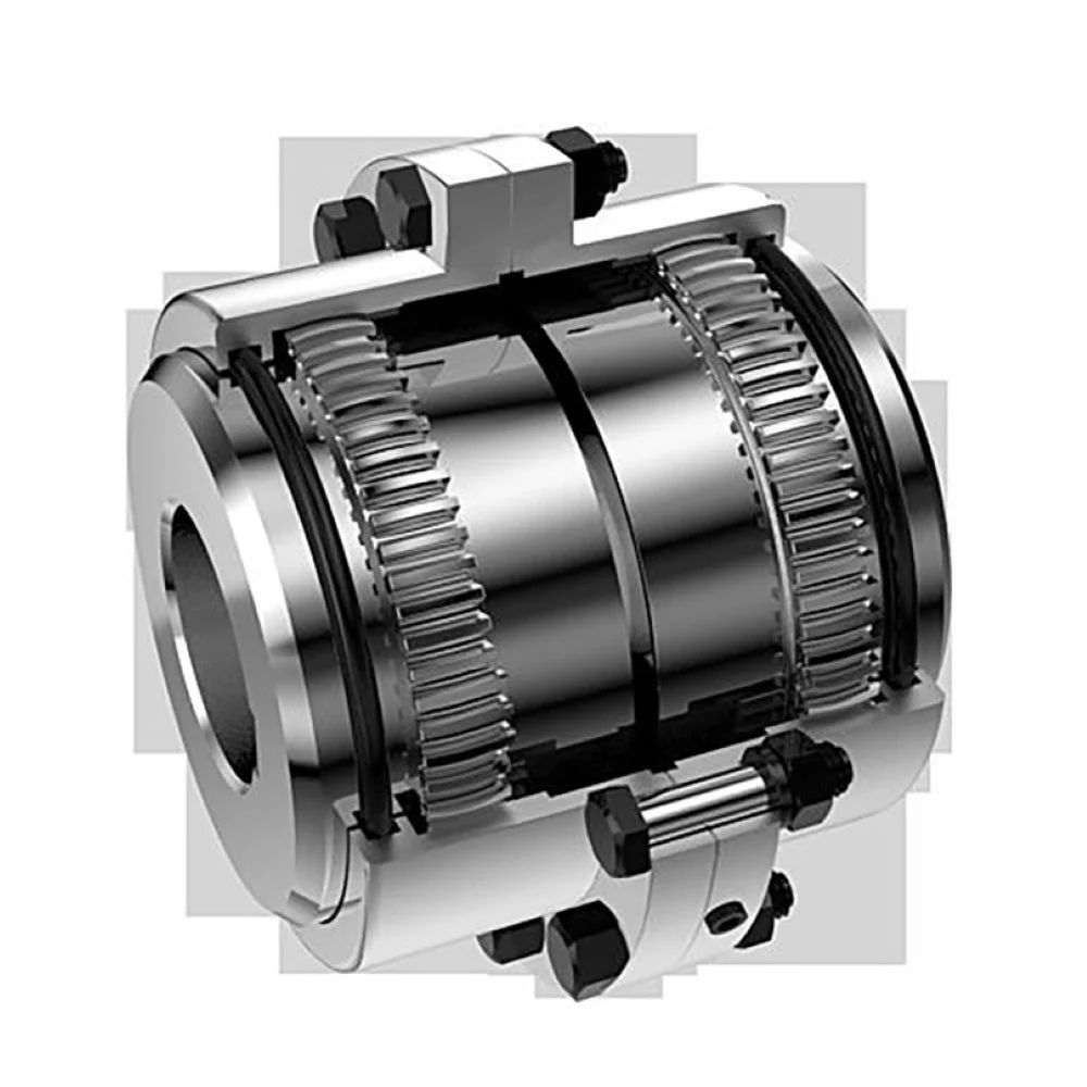
Tooth Couplings: Torque Transmission and Misalignment Handling
Tooth couplings are designed to efficiently transmit torque while accommodating certain levels of misalignment between connected shafts. Here’s how they handle torque transmission and misalignment:
Torque Transmission: Tooth couplings utilize interlocking teeth on the coupling hubs to transfer torque from one shaft to another. The teeth engagement creates a strong mechanical connection that can transmit high levels of torque. The coupling’s design ensures even distribution of torque across the teeth, minimizing stress concentrations and enhancing the coupling’s overall strength.
Misalignment Handling: Tooth couplings can accommodate a limited amount of angular and axial misalignment between shafts. The interlocking teeth provide some flexibility, allowing the coupling to compensate for small angular deviations. Additionally, the teeth engagement can provide a degree of axial flexibility, enabling the coupling to handle slight axial misalignments. However, tooth couplings have lower misalignment tolerance compared to some other flexible coupling types like elastomeric couplings.
It’s important to note that excessive misalignment can lead to premature wear and reduced coupling life. Therefore, while tooth couplings offer misalignment compensation to a certain extent, proper alignment of the connected shafts is still essential to ensure optimal coupling performance and longevity.


editor by CX 2024-04-24
by
Leave a Reply